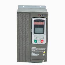
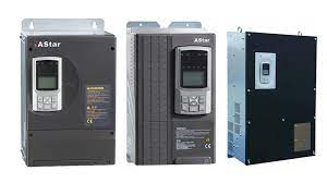
Biến tần Step AS180
Bảo hành: Chính hãng theo quy định của nhà sản xuất
Chứng từ: hóa đơn VAT đầy đủ
Giới thiệu chung biến tần STEP AS180:
|
AS 180 |
|
|
|
Model |
AS180 Fan & Pump Drives |
|
|
Applicable Motor (kW) |
2.2-630 |
|
|
Overload |
120%, 60s |
|
|
Output frequency |
V / F control: 0.00-300.00Hz |
|
|
Applicable Motor Type |
Induction motor |
|
|
control method |
V / F control |
High-performance V / F control |
|
Starting torque |
2.50Hz 120% |
0.5Hz 120% |
|
Speed range |
1:50 |
1: 200 |
|
Steady speed precision |
± 2% |
± 0.5% |
|
Built-in brake unit |
30kW and below |
|
|
Built-in DC reactor |
30kW and above |
|
|
Applications |
Light load, overload 120% 1 minute
|
|
|
Power input |
Input Voltage |
380-460V (-15% ~ + 10%), three-phase |
|
Input Frequency |
45-65Hz |
|
|
Allowable voltage fluctuation |
Voltage unbalance <3% |
|
|
Instant-drop |
Three-phase AC380-460V power supply, under voltage protection will work in 15ms if the input voltage is lower than AC300V |
|
|
Power output |
Voltage |
0 VAC ~ Input voltage |
|
Overload Class |
Stable working in the case of 40 ℃, heavy duty 150%, 1min |
|
|
Efficiency (full load) |
≥0.94 |
|
|
Output frequency accuracy |
± 0.01% (digital command -10 ~ + 45 ℃) ; ± 0.1% (simulation instruction 25 ± 10 ℃) |
|
|
Digital I / O |
Opto-isolated input |
7 channels, 24V high active low can be set, input function can be defined |
|
Open collector |
2 channels, Output functions can be defined |
|
|
Relay output |
2 channels, normally open contacts, contact capacity: inductive, 1.5A / 250VAC, output function defined |
|
|
Analog I / O |
Analog Input Voltage |
2 channels, accuracy 0.1%; Voltage:-10V~ + 10VDCOr Current: 0-20mA optional signal |
|
Analog voltage output |
2 channels, accuracy 0.1%; Voltage:-10V~ + 10VDCOr Current: 0-20mA optional signal |
|
|
Control characteristics |
Carrier frequency |
1.1-8 kHz; load characteristics, the carrier frequency can be automatically adjusted |
|
Frequency setting resolution |
0.01Hz (digital command),± 0.06Hz / 120Hz (11bit + unsigned analog instruction) |
|
|
Run command channel |
operation panel, control terminal, communication |
|
|
frequency Setting channel |
operation panel, digital/analog input, communication, performance function setting |
|
|
Torque boost |
Automatic torque boost; Manual torque boost |
|
|
V/F curve |
V/F Curve linear V/F And three curves of torque-derating can be defined |
|
|
Automatic voltage regulation (AVR) |
The output PWM can be Automatically adjusted according to the fluctuation of the bus, thereby reducing the influence of voltage fluctuations of the output voltage ripple |
|
|
non-stop operation |
in case of instant power failure, uninterrupted operation can be guaranteed by controlling the bus voltage |
|
|
DC braking capacity |
Braking current:0.0~120.0% Of rated current |
|
|
Special feature |
Parameter copy |
Parameter upload and download can be achieved via operating panel with the progress bar |
|
Process PID |
It can be used for closed-loop control of the process |
|
|
Common DC bus |
Full power range supports the common DC bus |
|
|
Motor protection |
Locked rotor |
|
|
Motor overload |
||
|
Speed limit |
||
|
Frequency Drive protection |
Output current limit |
|
|
Inverter overload |
||
|
IGBT I²t overload |
||
|
Input Supply Undervoltage / Overvoltage |
||
|
DC bus under-voltage / overvoltage |
||
|
IGBT overheating |
||
|
Radiator overheating |
||
|
electricity failure |
||


